Оставить сообщение
Если вас заинтересовала наша продукция и вы хотите узнать больше подробностей, пожалуйста, оставьте сообщение здесь, мы ответим вам как можно скорее.

Руководство по ремонту двигателя пожарной машины Isuzu NPR 4HK1
Руководство по техническому обслуживанию двигателя Isuzu Fire Truck 4HK1-TC, также называемое руководством по ремонту двигателя. Пожарная машина Isuzu или инженерная книга Пожарный автомобиль Isuzu .
Двигатель Isuzu Fire Truck 4HK1-TC — это высокопроизводительный дизельный двигатель, широко используемый в пожарных машинах, известный своей надежностью, долговечностью и высокой эффективностью. Для обеспечения долгосрочной стабильной работы двигателя необходимы регулярное техническое обслуживание и ремонт. В данной статье кратко изложены основные положения руководства по техническому обслуживанию двигателя Isuzu Fire Truck 4HK1-TC, чтобы помочь обслуживающему персоналу лучше понять и использовать его.
1. Обзор двигателя
Двигатель 4HK1-TC — это 4-цилиндровый рядный турбодизельный двигатель рабочим объемом 5,2 литра и максимальной мощностью 190 лошадиных сил. В двигателе используется усовершенствованная система впрыска топлива Common Rail и электронный блок управления (ЭБУ) для достижения более высокой топливной эффективности и снижения выбросов.
2. Ежедневное техническое обслуживание
Ежедневное техническое обслуживание является основой для обеспечения нормальной работы двигателя. В руководстве по техническому обслуживанию подробно перечислены пункты, подлежащие ежедневному осмотру, включая проверку уровня масла и охлаждающей жидкости, очистку или замену воздушного фильтра, замену топливного фильтра и т. д. Кроме того, в руководстве также приводятся рекомендации по регулярной замене моторного масла и масляного фильтра, обычно каждые 5000 километров или каждые 6 месяцев.
3. Диагностика неисправностей
Руководство по техническому обслуживанию содержит подробное описание процесса диагностики неисправностей, помогающее обслуживающему персоналу быстро находить и устранять проблемы. В руководстве перечислены распространенные коды неисправностей и их значения, а также приведены соответствующие решения. Например, если двигатель работает с недостаточной мощностью, руководство поможет обслуживающему персоналу проверить топливную систему, турбокомпрессор, выхлопную систему и т. д.
4. Капитальный ремонт и замена деталей.
Для двигателей, требующих капитального ремонта или замены деталей, руководство по техническому обслуживанию содержит подробные инструкции и меры предосторожности. Например, при замене таких ключевых компонентов, как поршневые кольца, направляющие клапанов и подшипники, в руководстве подробно описаны этапы снятия и установки, а также необходимые инструменты и моменты затяжки.
5. Меры предосторожности
В руководстве по техническому обслуживанию особое внимание уделяется важности безопасной эксплуатации. Перед выполнением любых работ по техническому обслуживанию необходимо убедиться, что двигатель полностью остыл и электропитание отключено. Кроме того, в руководстве также содержатся рекомендации по использованию средств индивидуальной защиты, таких как перчатки, защитные очки и защитная одежда.
Раздел 1А
система управления двигателем
Оглавление
Страница
[if supportFields]> TOC \h \z \t "1A,1,1A-,2"
система управления двигателем
[if supportFields]>
4
[if gte mso 9]>
Меры предосторожности
[if supportFields]>
4
[if gte mso 9]>
Функции и принцип работы
[if supportFields]>
5
[if gte mso 9]>
Схема конфигурации компонентов
[if supportFields]>
21
[if gte mso 9]>
Схема цепи
[if supportFields]>
25
[if gte mso 9]>
Как диагностировать неисправность
[if supportFields]>
42
[if gte mso 9]>
Процедуры диагностики неисправностей с помощью диагностического прибора.
[if supportFields]>
48
[if gte mso 9]>
Обзор функциональной проверки
[if supportFields]>
50
[if gte mso 9]>
Расследование
[if supportFields]>
51
[if gte mso 9]>
Проверка системы управления двигателем
[if supportFields]>
53
[if gte mso 9]>
Список данных диагностического прибора для выявления неисправностей
[if supportFields]>
55
[if gte mso 9]>
Содержимое списка данных диагностического прибора для выявления неисправностей
[if supportFields]>
58
[if gte mso 9]>
Выходной сигнал диагностического прибора для выявления неисправностей
[if supportFields]>
64
[if gte mso 9]>
Сбой запуска диагностического прибора.
[if supportFields]>
65
[if gte mso 9]>
Сбой связи диагностического прибора (эталон)
[if supportFields]>
67
[if gte mso 9]>
Сбой связи с ECM (ссылка)
[if supportFields]>
71
[if gte mso 9]>
Подтверждение запуска системы
[if supportFields]>
74
[if gte mso 9]>
Подтверждение системы электрической цепи подсветки индикатора неисправности двигателя (MIL)
[if supportFields]>
77
[if gte mso 9]>
Подтверждение неисправности электрической цепи мигания индикатора неисправности двигателя (MIL)
[if supportFields]>
78
[if gte mso 9]>
Проверка системы управления рециркуляцией отработавших газов (EGR).
[if supportFields]>
80
[if gte mso 9]>
Проверка системы управления прогревом
[if supportFields]>
84
[if gte mso 9]>
Проверка системы управления ограничением подачи воздуха через выхлопной тормоз/воздухозаборник
[if supportFields]>
87
[if gte mso 9]>
Обзор диагностических кодов неисправностей (DTC)
[if supportFields]>
92
[if gte mso 9]>
Код ошибки DTC P0016 (код прошивки 16)
[if supportFields]>
95
[if gte mso 9]>
Код неисправности DTC P0087 (код прошивки 225)
[if supportFields]>
97
[if gte mso 9]>
Код ошибки DTC P0088 (код прошивки 118)
[if supportFields]>
103
[if gte mso 9]>
Код неисправности DTC P0089 (код прошивки 151)
[if supportFields]>
109
[if gte mso 9]>
Коды неисправности DTC P0091, P0092 (код прошивки 247)
[if supportFields]>
112
[if gte mso 9]>
Код неисправности DTC P0093 (код прошивки 227)
[if supportFields]>
116
[if gte mso 9]>
Коды неисправности DTC P0107, P0108 (код прошивки 32)
[if supportFields]>
122
[if gte mso 9]>
Коды ошибок DTC P0112, P0113 (код прошивки 22)
[if supportFields]>
127
[if gte mso 9]>
Коды ошибок DTC P0117, P0118 (код прошивки 23)
[if supportFields]>
132
[if gte mso 9]>
Коды неисправности DTC P0122, P0123 (код прошивки 43)
[if supportFields]>
137
[if gte mso 9]>
Коды ошибок DTC P0182, P0183 (код прошивки 211)
[if supportFields]>
142
[if gte mso 9]>
Коды неисправности DTC P0192, P0193 (код прошивки 245)
[if supportFields]>
147
[if gte mso 9]>
[if supportFields]> Коды неисправности DTC P0201, P0202, P0203, P0204 (коды прошивки 271, 272, 273, 274)................................................... 1A-157
Код ошибки DTC P0217 (код прошивки 542)...................................................................................................... 1A-170
Код ошибки DTC P0219 (код прошивки 543)...................................................................................................... 1A-172
Код неисправности P0234 (код прошивки 42)........................................................................................................ 1A-175
Код неисправности P0299 (код прошивки 65)........................................................................................................ 1A-178
Код неисправности P0335 (код прошивки 15)........................................................................................................ 1A-182
Код неисправности P0336 (код прошивки 15)........................................................................................................ 1A-187
Код неисправности P0340 (код прошивки 14)........................................................................................................ 1A-190
Код неисправности P0341 (код прошивки 14)........................................................................................................ 1A-195
Код неисправности P0380 (код прошивки 66)........................................................................................................ 1A-198
Код неисправности P0381 (код прошивки 67)........................................................................................................ 1A-201
Код неисправности P0404 (код прошивки 45)........................................................................................................ 1A-205
Код неисправности P0409 (код прошивки 44)........................................................................................................ 1A-208
Коды неисправности DTC P0477, P0478 (код прошивки 46)............................................................................................. 1A-212
Код неисправности P0500 (код прошивки 25)........................................................................................................ 1A-216
Коды неисправности P0502, P0503 (код прошивки 25)............................................................................................. 1A-218
Код неисправности P0563 (код прошивки 35)........................................................................................................ 1A-223
Код неисправности P0601 (код прошивки 53)........................................................................................................ 1A-225
Код ошибки DTC P0602 (код прошивки 154)...................................................................................................... 1A-226
Коды неисправности P0604, P0606, P060B (коды прошивки 153, 51, 36).................................................................... 1A-228
Код неисправности P0641 (код прошивки 55)........................................................................................................ 1A-230
Код неисправности P0650 (код прошивки 77)........................................................................................................ 1A-233
Код неисправности P0651 (код прошивки 56)........................................................................................................ 1A-237
Коды неисправности DTC P0685, P0687 (код прошивки 416).......................................................................................... 1A-241
Код неисправности P0697 (код прошивки 57)........................................................................................................ 1A-245
Код неисправности P1093 (код прошивки 227)...................................................................................................... 1A-248
Коды неисправности P1261, P1262 (код прошивки 34)............................................................................................. 1A-253
Код неисправности P1404 (код прошивки 45)........................................................................................................ 1A-255
Код неисправности P1621 (код прошивки 54)........................................................................................................ 1A-257
Коды неисправности P2122, P2123 (код прошивки 121).......................................................................................... 1A-258
Коды неисправности P2127, P2128 (код прошивки 122).......................................................................................... 1A-264
Код ошибки DTC P2138 (код прошивки 124)...................................................................................................... 1A-270
Коды неисправности P2146, P2149 (код прошивки 158).......................................................................................... 1A-273
Коды неисправности P2228, P2229 (код прошивки 71)............................................................................................. 1A-279
Код неисправности P253A (код прошивки 28)....................................................................................................... 1A-284
Код неисправности P256A (код прошивки 31)....................................................................................................... 1A-287
Код неисправности DTC U0073 (код прошивки 84)....................................................................................................... 1A-291
Диагностика симптомов................................................................................................................... 1A-296
Явления: прерывистость........................................................................................................ 1A-297
Симптом: Затрудненный запуск........................................................................................................ 1A-300
Явления: Скачкообразная работа двигателя, нестабильный холостой ход или остановка двигателя.................................................................... 1A-303
Явление: Высокая скорость холостого хода.................................................................................................... 1A-306
Симптом: Аварийная остановка......................................................................................................... 1A-307
Симптом: Экстренная смена..................................................................................................... 1A-309
Симптом: Недостаточная мощность, сбой в разгоне или задержка реакции........................................................... 1A-311
Явление: Прерывистая работа, отказ ускорения................................................................... 1A-314
Симптом: Шум от сгорания...................................................................................................... 1A-316
Симптом: Низкая топливная экономичность.................................................................................... 1A-317
Явление: черный дым из выхлопных газов................................................................................... 1A-319
Симптом: Белый дым из выхлопных газов.................................................................................. 1A-321
Основные параметры датчика.............................................................................................................. 1A-323
Специальные инструменты............................................................................................................................. 1A-325
Программа.............................................................................................................................................. 1A-326
Правило программирования...................................................................................................................... 1A-326
Программа.............................................................................................................................................. 1A-326
Обучение работе с топливным насосом.............................................................................................................. 1A-328
Регулировка............................................................................................................................... 1A-328
Использование инструментов для тестирования цепей
При проведении диагностики в соответствии с диагностической программой не используйте контрольную лампу для диагностики электрической системы трансмиссии, если не указано иное. Если для диагностической программы будет использоваться клемма щупа, используйте комплект адаптеров для проверки клемм 5-8840-2835-0.
Доступные на рынке электрические компоненты
Под доступными на рынке электрическими компонентами подразумеваются компоненты, приобретаемые на рынке для установки в автомобиль. Поскольку эти компоненты не учитываются на этапе проектирования автомобиля, следует обращать на них внимание при использовании.
Осторожность:
Имеющиеся на рынке электрические компоненты, питание и заземление которых должны быть подключены к цепи, не относящейся к цепи системы электрического управления.
Хотя можно использовать имеющиеся на рынке электрические компоненты, в некоторых случаях они могут вызывать функциональные неисправности системы управления электрооборудованием. К ним относятся устройства, не подключенные к электросистеме, например, мобильный телефон, радио. Поэтому при диагностике силового агрегата сначала проверьте, установлены ли такие имеющиеся на рынке электрические компоненты. Если да, снимите их с автомобиля. Если неисправность сохраняется после снятия компонентов, следуйте общей последовательности диагностики.
Повреждения, вызванные электростатическим разрядом.
Поскольку электронные компоненты в системе управления могут работать при чрезвычайно низком напряжении, они легко повреждаются из-за электростатического разряда (ЭСР). Некоторые электронные компоненты повреждаются статическим электричеством ниже 100 В, которое незаметно для человека. Для того чтобы ЭСР был ощутим для человека, требуется напряжение 4000 В. Во многих случаях статическое электричество переносится человеком, и наиболее распространенными являются трение и индукция.
● Когда человек двигается из стороны в сторону на сиденье, возникает электрическое поле, возникающее из-за трения.
● Когда человек в обуви с теплоизоляцией находится рядом с объектом, находящимся под сильным электрическим напряжением, в момент соприкосновения с землей возникает электростатическая индукция. Человек получает электрический разряд, когда заряды одинаковой полярности встречаются с зарядами противоположной полярности. Поскольку статическое электричество может нанести вред, следует обращаться с электронными компонентами осторожно и проводить их проверку.
Осторожность:
Для предотвращения повреждений, вызванных электростатическим разрядом, соблюдайте следующие правила:
● Не прикасайтесь к контактным выводам клемм блока управления двигателем (ECM) и электронным компонентам, припаянным к задней панели схемы ECM.
● Не распаковывайте парки, пока не будет завершена подготовка к частичной установке.
● Перед извлечением деталей из упаковки подключите корпус и заземление автомобиля.
● При перемещении из стороны в сторону на сиденье, при переходе из положения стоя в положение сидя, а также при работе с деталью на определенном расстоянии, перед установкой детали убедитесь, что она касается пола.
Система управления двигателем (Common Rail)
Обзор системы и подробная информация
Система управления двигателем — это электрическая система управления, предназначенная для обеспечения оптимального режима сгорания топлива в двигателе в зависимости от условий движения. Она состоит из следующих частей:
● Электронно-управляемая система впрыска топлива (система Common Rail)
● Система рециркуляции отработавших газов (EGR)
Кроме того, система управления двигателем включает в себя следующие функции управления системой.
● Система управления прогревом
● Мощность вращения двигателя
● Функция коммуникации и самодиагностики
[endif]
[if gte vml 1]>
Электронно-управляемая система впрыска топлива (типа Common Rail)
Система Common Rail включает в себя камеру высокого давления и форсунку. Камера высокого давления предназначена для хранения топлива под давлением и называется Common Rail; форсунка оснащена электронным электромагнитным клапаном для впрыска топлива под давлением в камеру сгорания. Поскольку управление впрыском (давление впрыска, скорость впрыска и время впрыска) осуществляется электронным блоком управления двигателем (ECM), система Common Rail позволяет независимо регулировать частоту вращения двигателя и нагрузку. Даже при низкой частоте вращения двигателя поддерживается стабильное давление впрыска, что значительно снижает удельный черный дым при запуске и разгоне дизельного двигателя. Благодаря такому управлению выхлопные газы становятся чище, объем выхлопных газов уменьшается, а мощность увеличивается.
Контроль объема впрыска
Она управляет вращением обмотки форсунки в соответствии с сигналом, получаемым от частоты вращения двигателя и положения педали акселератора, и, следовательно, регулирует объем впрыска топлива для достижения оптимального объема.
Регулирование давления впрыска
Для обеспечения впрыска топлива под высоким давлением даже при низких оборотах двигателя необходимо контролировать давление топлива в топливной рампе. Необходимо рассчитать соответствующее давление в топливной рампе в зависимости от оборотов двигателя и объема впрыскиваемого топлива, подать необходимое количество топлива через управляющий топливный насос и обеспечить его подачу в топливную рампу под давлением.
Контроль времени впрыска
Она заменяет функцию синхронизации и вычисляет соответствующее время впрыска топлива в зависимости от частоты вращения двигателя и объема впрыска, а затем управляет форсункой.
Регулирование скорости впрыска
Для повышения эффективности сгорания в цилиндре впрыскивают (предварительный впрыск) небольшое количество топлива для воспламенения. После воспламенения проводят второй впрыск (основной впрыск). Время и объем впрыска регулируют с помощью форсунки (катушки форсунки).
 [endif]
Топливная система
Система Common Rail состоит из двух топливных систем высокого давления.
● Впускная магистраль низкого давления: между топливным баком и топливным насосом высокого давления.
● Линия высокого давления: между топливным насосом и форсункой.
Топливо засасывается из топливного бака в топливный насос высокого давления и подается в него под давлением в топливную рампу Common Rail. На этом этапе... Сигнал от ЭБУ управляет клапаном регулирования всасывания (регулятором давления в топливной рампе) для контроля объема топлива, подаваемого в топливную рампу.
Схема топливной системы
[if gte vml 1]>
|
Ключ 1. Common Rail 2. Клапан ограничения давления 3. Обратный трубопровод форсунки 4. Инжектор 5. Трубка возврата топлива 6. Трубопровод подачи топлива |
7. Топливный бак 8. Вентиляционный клапан 9. Стартерный насос 10. Топливный фильтр (с маслоотделителем) 11. Обратный клапан 12. топливный насос высокого давления |
EGR (Рециркуляция отработавших газов)
Система рециркуляции отработавших газов (EGR) возвращает часть отработавших газов во впускной коллектор, тем самым снижая выбросы оксидов азота (NOx). Благодаря системе EGR достигается улучшение управляемости автомобиля и снижение выбросов отработавших газов. Управляющий ток от системы EGR приводит в действие электромагнитный клапан и, следовательно, регулирует подъем клапана EGR. Кроме того, эта система определяет фактический подъем клапана с помощью датчика положения клапана EGR для обеспечения точного управления системой рециркуляции отработавших газов.
Система рециркуляции отработавших газов (EGR) начнет работать, когда будут достигнуты заданные параметры частоты вращения двигателя, температуры охлаждающей жидкости, температуры впускного воздуха и барометрического давления. Затем она будет определять степень открытия клапана в соответствии с частотой вращения двигателя и целевым объемом впрыска топлива. На основе рассчитанной степени открытия клапана она определяет нагрузку на привод электромагнитного клапана и затем управляет клапаном. Во время работы EGR дроссельная заслонка воздухозаборника будет закрыта, чтобы давление внутри впускного коллектора достигло целевого значения.
[if gte vml 1]>
[endif]
[if !mso]
|
[endif]
[if !mso]
|
[endif]
[if !mso]
|
[endif]
[if !mso]
|
|
Ключ 1. ЭМК 2. Датчик положения системы рециркуляции отработавших газов (EGR) 3. Клапан EGR 4. Охладитель системы рециркуляции отработавших газов (EGR) |
5. Впускной дроссельный клапан
|
Регулировка прогрева
Система управления прогревом
Система управления прогревом предназначена для облегчения запуска двигателя при низкой температуре и снижения количества белого дыма и шума. При активном выключателе стартера электронный блок управления двигателем (ЭБУ) определяет температуру охлаждающей жидкости двигателя на основе сигнала от датчика температуры охлаждающей жидкости двигателя (ECT), чтобы отрегулировать время прогрева и обеспечить соответствующие условия запуска двигателя. Кроме того, остаточное тепло, выделяемое при прогреве, позволяет поддерживать стабильную работу на холостом ходу. ЭБУ определяет время прогрева в зависимости от температуры охлаждающей жидкости двигателя, что приводит в действие реле прогрева и индикаторную лампу.
[endif]
[if gte vml 1]>
Обзор управления выхлопным тормозом
Выпускная труба выхлопного тормоза снабжена клапаном внутри. Закрытие клапана увеличивает сопротивление такту выпуска и усиливает эффект торможения двигателем. Клапан выхлопного тормоза работает в соответствии с вакуумным давлением. Вакуумное давление выхлопного тормоза регулируется открытием и закрытием электромагнитного клапана. ECM активирует электромагнитный клапан, если частота вращения двигателя превышает 575 об/мин и выполняются все условия работы выхлопного тормоза.
Условия работы выхлопного тормоза
● Выключатель выхлопного тормоза включен
● Педаль акселератора не нажата
● Отсутствие обнаружения неисправности датчика положения педали акселератора (APP), неисправности цепи выхлопного тормоза, неисправности выключателя сцепления, неисправности переключателя датчика APP, неисправности переключателя АЦП и т. д.
● Педаль сцепления не нажата
● Системное напряжение выше 24 В
● Скорость транспортного средства превышает установленный диапазон
ЭМК
Обзор ECM
[if gte vml 1]>
Электронный блок управления двигателем (ECM) постоянно отслеживает информацию со всех датчиков для управления трансмиссией. ECM выполняет функцию диагностики системы для выявления проблем в работе системы, оповещает водителя через индикатор неисправности двигателя (MIL) и одновременно записывает коды неисправностей (DTC). Коды DTC определяют неисправную зону, чтобы помочь специалисту по техническому обслуживанию.
Функции ЭБУ
Электронный блок управления двигателем (ЭБУ) выдает напряжение 5 В для питания различных датчиков и переключателей. Однако, поскольку питание осуществляется через сопротивление ЭБУ, контрольная лампа, подключенная к цепи, не загорится, даже если сопротивление очень высокое. В некоторых случаях обычный вольтметр не сможет показать правильные показания, поскольку его сопротивление слишком низкое. Для отображения правильных показаний убедитесь, что вы используете цифровой мультиметр с входным сопротивлением не менее 10 МОм (5-8840-2691-0). ЭБУ управляет цепью заземления или цепью питания через транзистор или другой блок и, следовательно, управляет выходной цепью.
ЭБМ и компоненты композитного материала
Электронный блок управления двигателем (ECM) позволяет добиться высокой управляемости и топливной экономичности при сохранении заданного уровня выбросов отработавших газов. ECM контролирует работу двигателя и автомобиля с помощью датчика положения коленчатого вала (CKP), датчика скорости автомобиля (VSS) и т. д.
Описание напряжения ЭБУ
Блок управления двигателем (ECM) подает стандартное напряжение на каждый переключатель и датчик. Это происходит потому, что сопротивление ECM очень высокое, в то время как напряжение, подаваемое на цепь, низкое. Контрольная лампа не загорится, даже если она подключена к цепи. Поскольку входное сопротивление вольтметра, обычно используемого механиками, очень низкое, иногда вольтметр не может показать правильные показания. В таком случае используйте цифровой мультиметр с входным сопротивлением 10 МОм (5-8840-2691-0), чтобы получить правильные показания напряжения.
Блок ввода/вывода ЭБУ оснащен аналого-цифровым преобразователем, демпфированием сигнала, счетчиком и специальным исполнительным механизмом. ЭБУ может управлять большинством компонентов агрегата через электронный переключатель.
EEPROM
EEPROM — это микросхема постоянного хранения данных, припаянная к задней панели блока управления двигателем (ECM). Для управления силовым агрегатом ECM передает необходимую программу и калибровочные сообщения в EEPROM.
В отличие от ПЗУ, EEPROM заменить нельзя. Если обнаружена неисправность EEPROM, замените блок управления двигателем (ECM) напрямую.
Вопросы, которые следует учитывать при ремонте блока управления двигателем (ECM).
Блок управления двигателем (ECM) способен выдерживать общий ток, характерный для движения автомобиля. Не допускайте перегрузки цепи. Во время проверки на обрыв и короткое замыкание не подключайте цепь ECM к заземляющему проводу и не подавайте напряжение, если это не указано иным образом. Для таких проверок цепи используйте цифровой мультиметр (5-8840-2691-0).
 [endif]
Топливный насос высокого давления является основной частью электронной системы впрыска топлива Common Rail. Топливный насос устанавливается в передней части двигателя. В состав топливного насоса входят регулятор давления Common Rail и датчик температуры топлива (FT).
Топливо подается в топливный насос высокого давления из топливного бака через внутренний подающий насос (роторного типа). Подающий насос подает топливо в два плунжерных отсека топливного насоса высокого давления. Подача топлива в плунжерный отсек регулируется регулятором давления в топливной рампе. Регулятор давления в топливной рампе управляется только током питания от ЭБУ. Подача топлива достигнет максимума, если ток на электромагнитный клапан не подается. И наоборот, подача топлива прекратится, когда ток на электромагнитный клапан достигнет максимума. По мере вращения двигателя два плунжера создают высокое давление в топливной рампе. Это управляет регулятором давления в топливной рампе в соответствии с сигналом от ЭБУ и, следовательно, регулирует объем и давление топлива в топливной рампе. Таким образом, достигается оптимальное рабочее состояние для повышения топливной экономичности и снижения выбросов NOx.
[if gte vml 1]>
Ключ
1. Датчик температуры топлива (ТТ)
2. Клапан регулирования всасывания (регулятор давления в общей топливной магистрали)
Клапан регулирования всасывания (регулятор давления в общей топливной магистрали)
Электронный блок управления двигателем (ЭБУ) контролирует коэффициент нагрузки регулятора давления в топливной рампе (время включения регулятора давления в топливной рампе) для регулирования объема топлива, подаваемого в плунжер высокого давления. Для достижения желаемого давления в рампе подается необходимое количество топлива, чтобы снизить нагрузку на привод топливного насоса высокого давления. При подаче тока на регулятор давления в топливной рампе генерируется переменная электродвижущая сила, соответствующая коэффициенту нагрузки, которая изменяет степень открытия топливопровода и, следовательно, регулирует объем топлива. Когда регулятор давления в топливной рампе выключен, пружина отводится, топливопровод полностью открывается, и топливо поступает в плунжер (максимальный впуск и максимальный выпуск). При открытом регуляторе давления в топливной рампе топливопровод закрывается (нормально открыт) под действием пружины. Благодаря открытию и закрытию регулятора давления в топливной рампе подается топливо, соответствующее рабочей нагрузке, а затем оно вытекает из плунжера.
Датчик температуры топлива (FT)
Датчик температуры топлива (FT-датчик) установлен на топливном насосе высокого давления, и его сопротивление изменяется в зависимости от температуры. Сопротивление будет низким при высокой температуре топлива и высоким при низкой температуре топлива. Электронный блок управления двигателем (ECM) подает на FT-датчик напряжение 5 В через нагрузочный резистор и, исходя из изменения напряжения, определяет температуру топлива для управления топливным насосом высокого давления. Напряжение будет низким при низком сопротивлении (высокой температуре) и высоким при высоком сопротивлении (низкой температуре).
Общая железная дорога
[if gte vml 1]>
Ключ
1. Клапан ограничения давления
2. Датчик давления в топливной рампе
В системе впрыска топлива с электрическим управлением типа Common Rail, топливная рампа расположена между топливным насосом высокого давления и форсункой и служит для хранения топлива под высоким давлением. На рампе установлены датчик давления и ограничительный клапан. Датчик давления определяет давление топлива в рампе и передает сигнал в электронный блок управления двигателем (ЭБУ). На основе этого сигнала ЭБУ регулирует давление топлива в рампе с помощью регулятора давления топливного насоса. Если давление топлива в рампе слишком высокое, ограничительный клапан открывается, чтобы сбросить давление.
Датчик давления в топливной рампе
Датчик давления в топливной рампе устанавливается на саму рампу для определения давления топлива и преобразования этого давления в напряжение. Чем выше давление, тем выше напряжение; чем ниже давление, тем ниже напряжение. Электронный блок управления двигателем (ECM) вычисляет фактическое давление в топливной рампе (давление топлива) на основе сигнала напряжения от датчика для управления впрыском топлива.
Клапан ограничения давления
[if gte vml 1]>
Ключ
1. Клапан
2. Корпус клапана
3. Направляющая клапана
4. Весна
5. Жилье
6. Топливный патрубок
7. Топливный выход
В случае аномально высокого давления ограничительный клапан откроется для сброса давления. Клапан откроется, когда давление внутри топливной рампы превысит 220 МПа, и закроется, когда давление опустится ниже 50 МПа. Топливо, выходящее из ограничительного клапана, поступит в топливный бак.
Форсунка
[if gte vml 1]>
Ключ
1. Болт крепления проводки
2. Вернуться в отдел монтажа трубопроводов.
3. Уплотнительное кольцо
4. Часть, касающаяся установки инжекционной трубы.
5. Идентификационная маркировка
6. Идентификационный код форсунки
По сравнению с более ранними форсунками, форсунка с электрическим управлением, управляемая ЭБУ, оснащена управляющим поршнем и электромагнитным клапаном. Эта информация записывается в идентификационный код (24 английских цифры) для отображения характеристик форсунки. Эта система регулирует объем впрыска для достижения оптимального эффекта с использованием информации о потоке форсунки (идентификационный код). При установке новой форсунки в автомобиль необходимо ввести идентификационный код в ЭБУ.
Для повышения точности объема впрыска используйте двумерный штрих-код или идентификационный код на форсунке. С помощью кода можно добиться децентрализованного управления объемом впрыска в каждой зоне давления, что повысит скорость сгорания, уменьшит выбросы и обеспечит стабильную работу двигателя.
[endif]
[if gte vml 1]>
● Без инъекций
Если электронный блок управления двигателем (ECM) не подает питание на электромагнитный клапан через двухходовой клапан (TWV), он закроет выходное дроссельное отверстие силой поршня. В этот момент давление топлива, подаваемое на переднюю часть форсунки, будет уравновешиваться с давлением топлива, подаваемым в отсек управления через впускной коллектор. В этом состоянии баланса давления сумма давления, приложенного к управляющему поршню и силе тяжести поршня форсунки, будет выше, чем давление, приложенное к передней части форсунки. Следовательно, форсунка будет опущена вниз, закрывая впрыскивающее отверстие.
● Инъекция
Если блок управления двигателем (ECM) подает питание на электромагнитный клапан, клапан управления тягой (TWV) срабатывает, открывая выходное дроссельное отверстие, и топливо поступает в маслоотводящий патрубок. В этот момент форсунка и управляющий поршень поднимаются одновременно под действием давления, приложенного к передней части форсунки. Затем открывается инжекционное отверстие форсунки для впрыска топлива.
● Конец инъекции
Когда блок управления двигателем (ECM) перестает подавать питание на электромагнитный клапан, давление в форсунке (TWV) падает, и выходное отверстие закрывается. В этот момент топливо не может поступать в обратный патрубок из диспетчерской, и давление топлива внутри быстро возрастает. Затем форсунка нажимается управляющим поршнем, закрывая впрыскивающий патрубок, после чего впрыск топлива прекращается.
Датчик температуры охлаждающей жидкости двигателя (ECT)
[if gte vml 1]>
Датчик температуры охлаждающей жидкости (ECT) установлен рядом с корпусом термостата, и сопротивление терморезистора изменяется в зависимости от изменения температуры. Сопротивление будет ниже при высокой температуре охлаждающей жидкости двигателя и выше при низкой температуре охлаждающей жидкости двигателя. ECM подает напряжение 5 В на датчик ECT через нагрузочный резистор и рассчитывает температуру охлаждающей жидкости двигателя в соответствии с изменением напряжения для управления впрыском топлива. Напряжение будет низким при низком сопротивлении (высокой температуре) и высоким при высоком сопротивлении (низкой температуре).
Датчик положения распределительного вала (CMP)
[if gte vml 1]>
Ключ
1. Шестерня распределительного вала
2. Направление вращения
3. Датчик положения распределительного вала (CMP)
Датчик положения распредвала (CMP) установлен в задней части головки блока цилиндров. Распредвал генерирует сигнал CMP, проходящий через датчик. Электронный блок управления двигателем (ECM) определяет состояние цилиндров и угол поворота коленчатого вала в соответствии с сигналом CMP и входным сигналом датчика положения коленчатого вала (CKP) для управления впрыском топлива и расчета частоты вращения двигателя. Хотя эти системы управления, как правило, основаны на сигнале CKP, в случае неисправности датчика CKP они будут работать в соответствии с сигналом CMP.
Датчик положения коленчатого вала (CKP)
[if gte vml 1]>
Ключ
1. Датчик положения коленчатого вала (CKP)
Датчик положения коленчатого вала (CKP) установлен в корпусе маховика. Когда отверстие в маховике проходит через датчик, он генерирует сигнал CKP. Электронный блок управления двигателем (ECM) определяет состояние цилиндров и угол поворота распределительного вала в соответствии с сигналом CKP и входным сигналом датчика положения коленчатого вала (CMP) для управления впрыском топлива и расчета частоты вращения двигателя. Хотя эти системы управления, как правило, основаны на сигнале CKP, в случае неисправности датчика CKP они будут работать в соответствии с сигналом CMP.
Датчик положения педали акселератора (APP) 1
[if gte vml 1]>
Датчик положения педали акселератора (APP) устанавливается на кронштейн управления педалью акселератора. Этот датчик состоит из двух датчиков в одном корпусе. ECM определяет целевые значения ускорения и замедления с помощью датчика APP. Датчик APP представляет собой датчик с отверстием типа 1C. Напряжение сигнала изменяется пропорционально изменению угла наклона педали акселератора. Напряжение сигнала датчика APP 1 низкое на начальном этапе и увеличивается по мере нажатия педали. Напряжение сигнала датчика APP 2 высокое на начальном этапе и уменьшается по мере нажатия педали.
Датчик скорости автомобиля
[if gte vml 1]>
Датчик скорости автомобиля (VSS) установлен на трансмиссии. Датчик скорости автомобиля оснащен схемой на основе эффекта Холла. Магнит и выходной вал при совместном вращении создают магнитное поле, а затем, взаимодействуя с магнитным полем, генерируют импульсный сигнал.
Датчик атмосферного давления
[if gte vml 1]>
Датчик барометрического давления установлен на приборной панели и изменяет напряжение сигнала в зависимости от давления. Электронный блок управления двигателем (ECM) обнаруживает низкое напряжение сигнала, когда давление низкое в высокогорной местности; наоборот, он обнаруживает высокое напряжение сигнала, когда давление высокое. С помощью этих сигналов напряжения ECM может регулировать объем и время впрыска топлива в соответствии с высотой над уровнем моря.
Датчик температуры всасываемого воздуха (IAT)
[if gte vml 1]>
Датчик температуры всасываемого воздуха (IAT)
Датчик температуры воздуха на впуске (IAT) установлен в направляющей трубке между воздушным фильтром и турбокомпрессором. При низкой температуре воздуха сопротивление датчика высокое. При повышении температуры воздуха сопротивление датчика снижается. При высоком сопротивлении датчика блок управления двигателем (ECM) обнаруживает высокое напряжение в сигнальной цепи. При низком сопротивлении датчика блок управления двигателем (ECM) обнаруживает низкое напряжение в сигнальной цепи.
клапан EGR
[if gte vml 1]>
Клапан рециркуляции отработавших газов (EGR) установлен на впускном коллекторе. Электронный блок управления двигателем (ECM) контролирует открытие клапана EGR в зависимости от режима работы двигателя. На основе сигнала коэффициента заполнения от ECM он управляет магнитной катушкой в клапане EGR. С помощью датчика положения он может определять степень открытия клапана EGR. Датчик положения имеет 3 положения в клапане EGR, определяющих 3 точки соответственно. Датчики положения 1, 2, 3 представляют собой штыревые отверстия типа 1C. Датчик положения передает сигнал о состоянии открытия/закрытия клапана, пропорциональном изменению степени открытия клапана EGR.
Датчик давления во впускном коллекторе
[if gte vml 1]>
Датчик давления всасываемого воздуха устанавливается на воздухозаборном патрубке для определения давления всасываемого воздуха и преобразования его в напряжение. Электронный блок управления двигателем (ЭБУ) обнаруживает высокое напряжение, когда давление высокое, и низкое напряжение, когда давление низкое. ЭБУ регулирует давление всасываемого воздуха в соответствии с сигналом напряжения от датчика для управления впрыском топлива и турбокомпрессором.
Индикатор неисправности двигателя
[if gte vml 1]>
Индикатор неисправности двигателя установлен на приборной панели, чтобы напомнить водителю о неисправности двигателя или связанных с ним систем. Когда блок управления двигателем (ECM) обнаруживает неисправность с помощью функции самодиагностики, индикатор неисправности двигателя загорается. Чтобы индикатор неисправности двигателя начал мигать, замкните контакты разъема диагностического кабеля (DLC). После этого можно подтвердить обнаружение кода неисправности (DTC).
Разъем канала передачи данных (DLC)
[if gte vml 1]>
Разъем DLC расположен в левом нижнем углу корпуса водителя и служит для связи диагностического прибора и каждого блока управления. Он оснащен функцией переключения диагностики. При коротком замыкании разъема DLC можно активировать переключатель диагностики.
Схема конфигурации компонентов
компоновка деталей двигателя
( 1/2 )
[if gte vml 1]>
|
Ключ 1. Датчик температуры охлаждающей жидкости двигателя (ECT) 2. Форсунка (в крышке головки цилиндра) 3. Средний соединитель жгута проводов форсунки |
4. Клапан EGR 5. Датчик давления в топливной рампе 6. Клапан ограничения давления 7. Клапан регулирования всасывания (регулятор давления в общей топливной магистрали) 8. Датчик температуры топлива (FT) |
( 2/2 )
[if gte vml 1]>
Ключ
1. Датчик положения коленчатого вала (CKP)
2. Датчик положения распредвала (CMP)
Схема расположения деталей двигателя 1
[if gte vml 1]>
Ключ
1. ЭМК
2. Клеммный резистор
компоновка деталей двигателя 3
[if gte vml 1]>
|
Ключ 1. Стойка для вентиляционных отверстий 2. Бардачок (маленький) 3. Нагревательный блок, панель управления размораживателем, панель управления кондиционером. 4. Радиокассетный или CD-проигрыватель 5. Бардачок (большой) 6. Стеклоочиститель, рычаг переключателя омывателя, рычаг переключателя вспомогательного тормоза выхлопной системы 7. Рычаг переключения кластера 8. Рычаг блокировки регулировки рулевого колеса 9. Переключатель аварийной сигнальной лампы |
10. Зажигалка 11. Футляр для карт 12. Крючок 13. Скрытый подстаканник 14. Крышка блока предохранителей 15. Ящик с инструментами |
Схема электрической цепи (1/2)
[endif] [if gte vml 1]>
( 2/2 )
[if gte vml 1]>
[endif]
[if !mso]
|
[endif]
[if !mso]
|
[endif]
[if !mso]
|
[endif]
[if !mso]
|
[endif]
[if !mso]
|
[endif]
[if !mso]
|
[endif]
[if !mso]
|
[endif]
[if !mso]
|
[endif]
[if !mso]
|
[endif]
[if !mso]
|
[endif]
[if !mso]
|
[endif]
[if !mso]
|
[endif]
[if !mso]
|
[endif]
[if !mso]
|
[endif]
[if !mso]
|
[endif]
[if !mso]
|
[endif]
[if !mso]
|
[endif]
[if !mso]
|
[endif]
[if !mso]
|
[endif]
[if !mso]
|
[endif]
[if !mso]
|
[endif]
[if !mso]
|
Terminal arrangement
[if gte vml 1]>
[endif]
[if !mso]
|
ECM terminal end view
ECM
[if gte vml 1]>
|
Joint SN |
J-14 |
|
|
Joint color |
Black |
|
|
Test adapter SN |
J-35616-64A |
|
|
Port No. |
Wire color |
Port function |
|
1 |
Black |
ECM signal ground |
|
2 |
Red |
Battery voltage |
|
3 |
Black |
ECM signal ground |
|
4 |
Black |
ECM signal ground |
|
5 |
Red |
Power voltage |
|
6 |
Blue/Red |
Malfunction Indicator Lamp (MIL) Control |
|
7 |
Blue/Pink |
Exhaust brake lamp control |
|
8 |
Light green |
Engine speed signal output to tachometer |
|
9 |
Light green/Black |
DPD indicator lamp control (Euro IV) |
|
10 |
Black/Red |
Glow plug relay control |
|
11 |
Orange/Blue |
Warming-up lamp control |
|
12 |
- |
Not used |
|
13 |
- |
Not used |
|
14 |
White/blue |
Starter on/off relay control |
|
15 |
Light green/white |
Exhaust brake solenoid valve control |
|
16 |
Blue/yellow |
Check oil residual volume warning lamp control |
|
Joint SN |
J-14 |
|
|
Joint color |
Black |
|
|
Test adapter SN |
J-35616-64A |
|
|
Port No. |
Wire color |
Port function |
|
17 |
Blue/Black |
SVS indicator lamp control (Euro IV) |
|
18 |
Сине-белый |
Входной сигнал CAN высокого уровня |
|
19 |
Жёлтый/зелёный |
Сигнал датчика скорости автомобиля или электронный гидравлический блок управления |
|
20 |
Черный |
Датчик положения педали акселератора 1, заземление экрана |
|
21 |
Синий/Черный |
Управление главным реле ЭБУ |
|
22 |
Зеленый |
Низкий входной сигнал датчика воздушного потока (Евро IV) |
|
23 |
Желтый |
Опорное значение датчика расхода воздуха 12 В (Евро IV) |
|
24 |
Жёлтый/Чёрный |
Напряжение зажигания |
|
25 |
Красно-белый |
сигнал главного переключателя круиз-контроля |
|
26 |
Коричнево-жёлтый |
Сигнал выключателя педали сцепления |
|
27 |
- |
Не используется |
|
28 |
- |
Не используется |
|
29 |
- |
Не используется |
|
30 |
- |
Не используется |
|
31 |
- |
Не используется |
|
32 |
- |
Не используется |
|
33 |
Розовый |
Сигнал переключателя холодильной машины |
|
34 |
Зеленый/Оранжевый |
сигнал переключателя кондиционера |
|
35 |
Зеленый/белый |
резистор, понижающий напряжение |
|
36 |
- |
Не используется |
|
37 |
Синий |
CAN снижает входной сигнал |
|
38 |
Светло-голубой |
Ключевые слова 2000 строк данных (не относящиеся к стандарту Euro IV) |
|
39 |
Черный |
Датчик положения педали акселератора 2 и датчик расхода воздуха (Евро IV) заземление экрана |
|
40 |
Синий/Черный |
Управление главным реле ЭБУ |
|
41 |
Розовый/чёрный |
Датчик положения педали акселератора 1, датчик холостого хода, датчик положения ВОМ, низкий входной сигнал |
|
Совместная СН |
J-14 |
|
|
Цвет соединения |
Черный |
|
|
Тестовый адаптер SN |
J-35616-64A |
|
|
Номер порта |
Цвет провода |
Функция порта |
|
42 |
Красный |
Датчик положения педали акселератора 1, датчик холостого хода, датчик положения ВОМ, питание 5 В. |
|
43 |
Черный |
Сигнальная земля ЭБУ |
|
44 |
Синий/Оранжевый |
Сигнал переключателя ВОМ |
|
45 |
Светло-зелёный/красный |
Сигнал выключателя тормоза выхлопной системы |
|
46 |
Красно-белый |
Сигнал выключателя зажигания |
|
47 |
Белый/Красный |
Сигнал переключения DPD (Евро IV) |
|
48 |
Белый/чёрный |
сигнал выключателя стояночного тормоза |
|
49 |
- |
Не используется |
|
50 |
Черный/синий |
Сигнал нейтрального выключателя |
|
51 |
Светло-зелёный/синий |
Сигнал переключателя предварительного подогрева двигателя |
|
52 |
Желтый |
Переключатель диагностики |
|
53 |
Бесцветный/жёлтый |
сигнал переключателя объема моторного масла |
|
54 |
- |
Не используется |
|
55 |
- |
Не используется |
|
56 |
- |
Не используется |
|
57 |
- |
Не используется |
|
58 |
Сине-белый |
Входной сигнал CAN высокого уровня (Евро IV) |
|
59 |
Черный |
Заземление экрана датчика перепада давления в выхлопных газах |
|
60 |
Черный |
Датчик положения педали акселератора 2, датчик барометрического давления и датчик температуры всасываемого воздуха — низкий входной сигнал |
|
61 |
Красный |
Датчик положения педали акселератора 2, датчик барометрического давления и питание воздухозаборника 5 В. |
|
62 |
Черный |
Сигнальная земля ЭБУ |
|
63 |
Сине-белый |
Сигнал датчика положения педали акселератора 1 |
|
64 |
Белый |
сигнал датчика положения педали акселератора |
|
65 |
|
сигнал переключателя круиз-контроля |
|
66 |
Синий/жёлтый |
Сигнал датчика холостого хода |
|
67 |
Светло-зелёный |
Сигнал датчика перепада давления в выхлопных газах (Евро IV) |
|
Совместная СН |
J-14 |
|
|
Цвет соединения |
Черный |
|
|
Тестовый адаптер SN |
J-35616-64A |
|
|
Номер порта |
Цвет провода |
Функция порта |
|
68 |
Черный |
Необязательно (GND) |
|
69 |
Синий |
Сигнал датчика воздушного потока (Евро IV) |
|
70 |
Коричневый |
Датчик положения ВОМ: |
|
71 |
Коричневый/зеленый |
Сигнал датчика барометрического давления |
|
72 |
Красный/Зеленый |
Сигнал датчика температуры впуска |
|
73 |
Жёлтый/Красный |
Сигнал датчика температуры выхлопных газов 1 (Евро IV) |
|
74 |
Красный |
Сигнал датчика температуры выхлопных газов 2 (Евро IV) |
|
75 |
- |
Не используется |
|
76 |
- |
Не используется |
|
77 |
- |
Не используется |
|
78 |
Синий |
Входной сигнал CAN с низким уровнем (стандарт Euro IV или с использованием граничного элемента) |
|
79 |
Черный |
Датчик перепада давления в выхлопных газах, датчик температуры выхлопных газов 1 и датчик температуры выхлопных газов 2 (низкий входной сигнал, Евро IV) |
|
80 |
Сине-белый |
Датчик перепада давления в выхлопных газах, питание 5 В (Евро IV) |
|
81 |
Черный |
Оболочка ECM GND |
[if gte vml 1]>


Вас может быть заинтересован в следующей информации
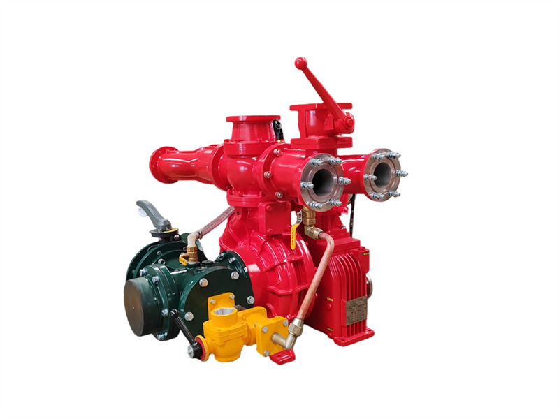
The пожарный насос CB10/60-RS, устанавливаемый на грузовой автомобиль состоит из одноступенчатого центробежного насоса низкого давления, двухпоршневого вакуумного насоса, устройства автоматического отключения электромагнитной муфты, повышающего редуктора, напорного трубопровода с запорным клапаном и всасывающего трубопровода. ♦ Основная конструкция и функции (1) Одноступенчатый центробежный насос низкого давления: Состоит из крышки насоса, корпуса насоса, рабочего колеса первой ступени и вала насоса, обеспечивает номинальное давление и номинальный расход. (2) Повышающий редуктор: Повышающий редуктор автомобильного пожарного насоса CB10/60-RS имеет стандартное передаточное отношение увеличения скорости 1.440. (3) Двухпоршневой вакуумный насос: В основном состоит из поршня, корпуса насоса, вала насоса и эксцентрикового колеса. Эксцентриковое колесо оснащено направляющей штангой поршня и стальной втулкой корпуса насоса. На обоих концах поршневого насоса установлены впускные и выпускные клапаны. При включении электромагнитной муфты поршневой насос начинает работать. Во время работы эксцентриковое действие эксцентрикового колеса заставляет поршень совершать возвратно-поступательное движение, постепенно удаляя воздух из насоса и трубопровода, тем самым улучшая качество удаления воздуха. Внутри полости создается вакуум для достижения цели забора воды. 1. Выходной запорный клапан (4 шт.); 2. Левая и правая выходные водяные трубы; 3. Соединитель обратной линии охлаждающей воды редуктора; 4. Соединитель манометра; 5. Выходной обратный клапан; 6. Фланец водяного ствола; 7. Реле давления воды; 8. Соединитель обратной линии воды под давлением охлаждения КОМ; 9. Фланец заднего водяного бака; 10. Шаровой клапан заднего водяного бака; 11. Редуктор; 12. Электромагнитная муфта и проводка; 13. Поршневой заливочный насос; 14. Соединитель вакуумметра; 15. Соединитель вакуумного заливочного устройства; 16. Интерфейс впускной трубы; 17. Четырехходовая впускная труба; 18. Сливной клапан водяного насоса; 19. Обратная линия воды под давлением охлаждения редуктора; 20. Впускная линия воды под давлением охлаждения редуктора; 21. Клапан уровня смазочного масла редуктора; 22. Соединительный фланец; 23. Приводной ремень; 24. Резьбовой соединитель воды под давлением дозатора пены (не устанавливается на автоцистернах для воды); 25. Интерфейс дозатора пены; 26. Выходной соединитель воды под давлением охлаждения КОМ; 27. Пожарный насос автомобиля CB10/60; 28. Выходной соединитель воды под давлением охлаждения редуктора; 29. Задний впускной дроссельный клапан (4) Трубопровод выпуска воды низкого давления и запорный клапан: Состоит из обратного клапана выпуска воды низкого давления, левой и правой труб выпуска воды, четырёх труб выпуска воды и четырёх запорных клапанов выпуска воды. (5) Задний трубопровод подачи воды: Состоит из четырёхходовой входной трубы, входного фильтрующего экрана, внешнего входного соединителя, а с обеих сторон четырёхходовой входной трубы: с правой...
Подробности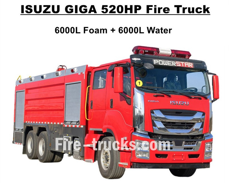
Высокое качествоПожарные автомобили ISUZU GIGAэкспорт в Западную Африку, Буркина-Фасо, которые спроектированы на базе тяжелого шасси грузовика ISUZU GIGA VC66 6x4, оснащены новой кабиной GIGA VC66, стандартным сиденьем с пневмоподвеской и кондиционером для комфортного вождения. Автомобиль оснащен дизельным двигателем японской технологии ISUZU модели 6WG1-TCG62 мощностью 520 л.с. и рабочим объемом 15681 куб. см, работает в паре с механической коробкой передач FAST с 12 ступенями, имеет очень низкий расход топлива, стандартные передние шины 385/80R22.5 и задние 315/80R22.5, всего 10+1 единиц. Комплекты надстройки включают цистерну для воды объемом 6000 л и цистерну для пены объемом 6000 л, изготовленные из нержавеющей стали #304, долговечной для длительного срока службы. Работает в паре с индивидуально настроенным сверхмощным пожарным насосом CB10/140 с эффективным расходом 140 л/с, с двойным пожарным насосом в верхней части надстройки цистерны, модель PL8/64 с эффективным расходом 64 л/с.Пожарный автомобиль ISUZU GIGA мощностью 520 л.с.оснащен всем необходимым пожарным оборудованием, является идеальным пожарным автомобилем для тушения пожаров и спасения людей, широко используется на рынке Буркина-Фасо. Пожарный автомобиль ISUZU GIGA 520 л.с. с пенным баком объемом 14000 л Завод CS TRUCKS является профессиональным производителем в области грузовых автомобилей,гарантирует, что вся продукция является абсолютно новой и высокого качества. Особенности пожарного автомобиля ISUZU: Название Пожарный автомобиль ISUZU GIGA с пенным насосом и баком объемом 12000 л Кабина GIGA VC66 Двигатель 6WG1-TCG62 мощностью 520 л.с. и рабочим объемом 15681 куб. см Коробка передач FAST 12 ступеней Колесная база 4600+1370 мм Шина Пере
Подробности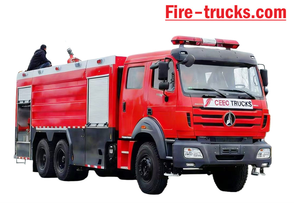
Бейбен Пожарный автомобиль на базе шасси и кузова типа II Beiben 2638 модели 6*4 с левосторонним рулевым управлением. Вместимость может достигать 12 000 литров, включая 10 000-литровый резервуар для воды и 2 000-литровый резервуар для пены. Пожарно-спасательная служба Бейбен 2638 грузовик Оснащен пожарным насосом XIONGZHEN CB10/60 и пожарным монитором PL8/48, что очень удобно для Ежедневное использование. В основном применяется для тушения пожаров в любых нуждающихся районах. Этот автомобиль разработан с учетом всех преимуществ оригинального шасси грузовика марки Beiben. В полной мере учтены удобство и надежность изделия, а также новая конструкция шасси. Корпус Материал – углеродистая сталь международного стандарта с антикоррозионным покрытием и нержавеющая сталь. может эффективно предотвращать ржавление и продлевать срок службы. Пожарная машина Beiben 6x4, оснащенная сэндвич-системой отбора мощности, пожарным насосом, пожарным монитором, комнатой для экипажа и пожарным рукавом. ящик, насосная станция, цистерна для сухого порошка и система подачи азота, соединенная с катушкой для шланга трубопровода, английский язык Блок управления версией, входной и выходной трубопроводы, задняя лестница для подъема, верхняя подушечная лампа и все необходимое. Противопожарное оборудование. Индивидуально спроектированная двухрядная кабина с сиденьями 2+4, обеспечивающая приятные ощущения от вождения. Поэтому, тот Этот автомобиль идеально подходит для пожаротушения, особенно в рамках противопожарных работ. [if gte mso 9]> Normal 0 7.8 磅 0 2 false false false EN-US ZH-CN X-NONE
Подробности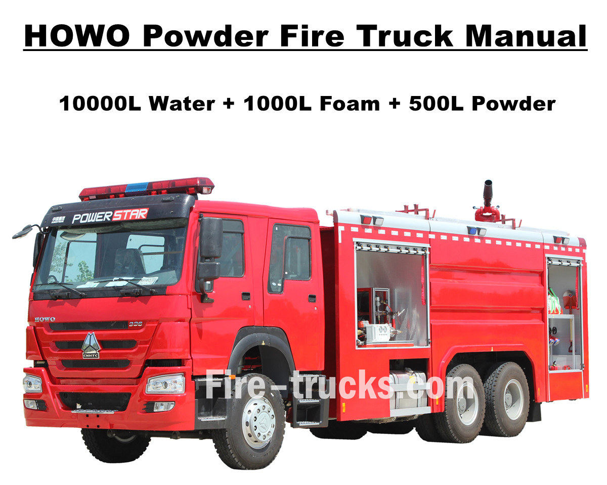
Клиент из Мавритании, Африка, приобрел в общей сложности 4 единицы. Насосная пожарная машина Sinotruk HOWO Пожарная машина HOWO, также известная как пожарный автомобиль или пожарная насосная машина, разработана и изготовлена для удовлетворения потребностей в различных проектах по тушению пожаров и спасению людей на международном уровне. Она оснащена двухместной кабиной для перевозки пожарных, различным противопожарным оборудованием и инструментами для тушения пожаров, спасательных работ и т.д. Для обеспечения более эффективной работы пожарных машин HOWO мы оснастили их алюминиевыми лестницами, водяной пеной и порошковым огнетушащим веществом, цистернами для хранения, эффективным пожарным насосом модели CB10/60 в сочетании с пожарным монитором PL8/48, обеспечивающим дальность струи более 70 м, пожарным рукавом с пистолетом для тушения пожаров на больших расстояниях, дыхательным аппаратом с маской, защитной одеждой, спасательными инструментами, аптечкой первой помощи и т.д. Все это обеспечивает эффективную и надежную работу пожарных машин HOWO. Для обеспечения более удобного и эффективного использования пожарных машин HOWO клиентами в Мавритании, все автомобили комплектуются полным набором сервисных каталогов на английском языке, включая руководство пользователя для ознакомления с эксплуатацией, руководство по эксплуатации автомобиля и каталог запасных частей для использования и технического обслуживания. Пожарный насосный автомобиль SINOTRUK HOWO 14 000 л фабрика POWERSTAR является профессиональным производителем грузовых автомобилей. Гарантируем, что вся продукция абсолютно новая и высокого качества. » Ⅰ. Преимущества пожарной машины HOWO: ★ Мощный дизельный двигатель WEICHAI мощностью 247 кВт / 336 л.с., 100 000 км пробега без проблем. ★ Классическая кабина SINOTRUK HOWO HW76, европейский дизайн ★ Установлен пожарный насос CB10/60, производительность 60 л/с, сверхнадежный. ★ Водомет PL8/48, устанавливаемый сверху, отличается высокой прочностью и долговечностью. ★ 500 л сухого порошка с азотным поддоном и клапанами регулирования подачи воздуха. ★ Интегрированная система управления пеной и порошком с панелью управления на задней панели. » II . Чертеж пожарной машины Howo Rescue: [if gte mso 9]> Normal 0 7.8 磅 0 2 false false false EN-US ZH-CN AR-SA /* Style Definitions */ table.MsoNormalTable {mso-style-name:普通表格; mso-tstyle-rowband-size:0; mso-tstyle-colband-size:0; mso-style-noshow:yes; mso-style-priority:99; mso-style-parent:""; mso-padding-alt:0cm 5.4pt 0cm 5.4pt; mso-para-margin:0cm; mso-pagination:widow-orphan; font-size:10.0pt; font-family:"Calibri",sans-serif; mso-bidi-font-family:"Times New Roman";} To guarantee Mauritania Nouakchott clients purchased satisfy HOWO 6x4 Water & Foam & Powder Fire Truck, so we POWERSTAR Engineer Department do design the truck firstly, then start for production. Howo fire truck equipped with Sandwich PTO, fire pump, fire monitor, crew room, hose box, pump room, English version control box, inlet and outlet pi...
Подробности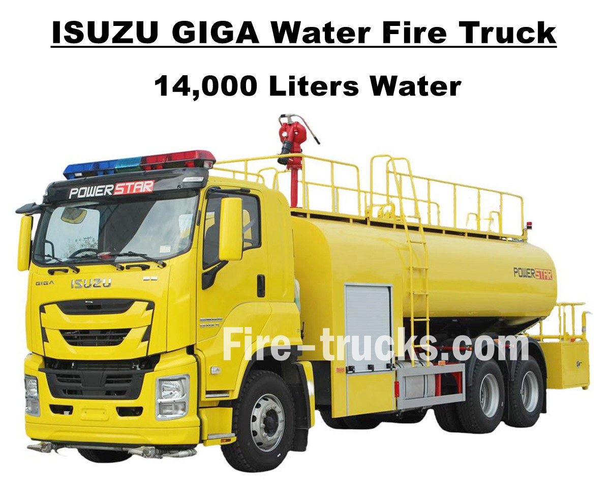
Покупатель из Южной Америки, г-н Джозеф из Гондуры, приобрел 1 единицу товара. Пожарный автомобиль Isuzu GIGA VC66 объемом 14000 л (3700 галлонов) от POWERSTAR TRUCKS, Разработанный на базе шасси японского тяжелого грузовика ISUZU GIGA 6x4, автомобиль оснащен дизельным двигателем 6UZ1-TCG60 мощностью 280 кВт / 380 л.с., представляющим собой 6-цилиндровый, 4-тактный двигатель с водяным охлаждением, турбонаддувом и промежуточным охлаждением, рабочим объемом 9839 мл, совместимый с международной стандартной механической коробкой передач FAST с 12 передачами переднего хода и 2 передачами заднего хода, что обеспечивает эффективное снижение расхода топлива. Всего установлено 13 стальных шин размером 12R22.5, включая одно запасное колесо, что отлично подходит для различных дорожных условий и горных восхождений. Колесная база может быть увеличена до 4600 + 1370 мм. Подходящая и удобная услуга по организации противопожарных мероприятий на различных территориях. Пожарная машина Isuzu GIGA 3700 галлонов с водовозом полностью основана на японских технологиях шасси грузовика ISUZU, оригинальный салон GIGA VC66 оснащен кондиционером с функциями обогрева и охлаждения для комфортного вождения. Кузов автоцистерны изготовлен из нержавеющей стали SS304, эффективный объем 14000 литров, что эквивалентно 3700 галлонам. Автоцистерна оснащена пожарным насосом китайского бренда CB10/60 и пожарным лафетным стволом PS8/50, полным комплектом пожарно-спасательного оборудования и индивидуальной лимонно-желтой окраской всего автомобиля. Все это делает автомобиль идеальным средством для тушения пожаров на улицах и в населенных пунктах Гондураса. Кроме того, автомобиль поставляется с полным каталогом на английском языке для обслуживания, включая руководство пользователя для руководства по эксплуатации, руководство по эксплуатации грузовика GIGA, руководство по запасным частям для технического обслуживания. Пожарный автомобиль Isuzu GIGA 14 000L с водяным насосом Завод POWERSTAR является профессиональным производителем в области грузовых автомобилей, Гарантируем, что вся продукция абсолютно новая и высокого качества. » Ⅰ. Преимущества пожарной машины Isuzu для тушения пожаров: ★ Мощный дизельный двигатель 6WG1 мощностью 280 кВт / 380 л.с., пробег 100 000 км без проблем. ★ ISUZU VC66 с новой GIGA-кабиной, европейским дизайном ★ Установлен пожарный насос CB10/60, производительность 60 л/с, сверхнадежный. ★ Установленная сверху водометная установка PS8/50, долговечная в эксплуатации. ★ Интегрированная система управления с боковой панелью. ★ Роспись лимонно-желтого цвета на заказ, блестящая и красивая Пожарный насос CB10/60 Модель : КБ10/60 Давление : 1,0 МПа Макс. рабочее давление : 1,232 МПа Скорость потока : 60 л/с при 1,0 МПа, скорость 3286±50 об/мин, мощность 102 кВт, глубина всасывания 3 м 42 л/с при 1,3 МПа, скорость 3519±50 об/мин, мощность 106 кВт, глубина всасывания 3 м 30 л/с при 1,0 МПа, скорость 3120±50 об/мин, мощность 73 кВт, глубина всасывания 7 м Коэффициент скорости ...
Подробности
Powerstar Trucks производит специальные автомобили для экстренных служб и Пожарные машины В течение нескольких лет компания Powerstar Trucks Emergency Response зарекомендовала себя как ведущий производитель полного спектра специализированного пожарного оборудования с опытом в пожарные машины с пеной и водой и спасательная пожарная машина . Опираясь на опыт, которому доверяют пожарные, грузовики Powerstar предлагают гибкие, стратегические и специализированные решения для удовлетворения уникальных потребностей каждой пожарной службы, ставя на первое место службы быстрого реагирования. 120 единиц спасательной пожарной машины для доставки 65 единиц пожарно-спасательных машин экспортированы в полицию Уганды Пожарные машины с водой Автомобиль пенного пожаротушения Пожарные автомобили в основном подразделяются на четыре категории в зависимости от их функций: пожарные автомобили, автолестницы, пожарные автомобили специального назначения и пожарные автомобили материально-технического обеспечения. 01, Пожарные машины являются основной силой непосредственного тушения пожаров, в том числе: * **Пожарные автомобили с водяным баком:** Оснащены собственным водяным баком и насосом, подходят для тушения пожаров общего назначения. * **Пенные пожарные машины:** Специально разработаны для тушения пожаров, связанных с легковоспламеняющимися жидкостями, такими как нефть. * **Пожарные машины с сухим порошком:** Подходят для тушения газовых и электрических пожаров. * **Пожарные машины с углекислым газом:** Используются для защиты ценного оборудования и точных приборов. * **Автомобили комбинированного применения пены и порошка:** Могут одновременно использовать оба огнетушащих вещества с широким спектром применения. 02, Пожарные автомобили с воздушными лестницами используются для спасательных работ и тушения пожаров в высотных зданиях, в том числе: * **Пожарные автомобили с лестничным механизмом:** Оснащены телескопической лестницей, способной спасать людей и тушить пожары на высоте. * **Пожарные машины с воздушным распылением:** используют дистанционно управляемую стрелу для распыления огнетушащих веществ на большие расстояния. * **Пожарные автовышки:** представляют собой гидравлическую подъемную платформу для спасательных и пожарных работ. Применение пожарной машины 03. Специализированные пожарные автомобили отвечают за выполнение определенных задач, таких как: * **Пожарные машины для спасения и ликвидации последствий стихийных бедствий:** Оснащены инструментами для сноса и подъемным оборудованием, используются для спасения при авариях. * **Освещение пожарных машин**: обеспечивает интенсивное освещение для спасательных операций в ночное время. * **Пожарные машины для удаления дыма:** Используются для операций по удалению дыма при подземных пожарах. 04. **Пожарные машины материально-технического обеспечения:** В первую очередь обеспечивают материально-техническую поддержку на месте пожара, например: * **Пожарные машины водоснабжения:** Обеспечивают постоянную подачу воды...
Подробности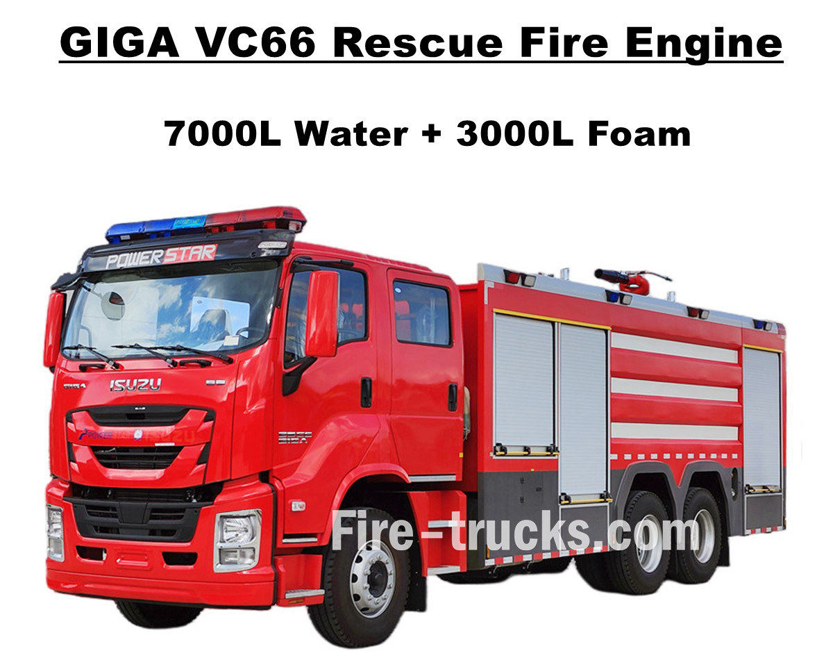
Клиенты из Манилы, Филиппины, совершили покупку. Пожарный автомобиль Isuzu GIGA VC66 повышенной грузоподъемности от POWERSTAR TRUCKS, который оснащен японским дизельным двигателем ISUZU 6WG1-TCG61 мощностью 338 кВт / 460 л.с., который является 6-цилиндровым, 4-тактным, с водяным охлаждением, турбонаддувом и промежуточным охлаждением, расчетный стандартный рабочий объем 15681 куб.см., соответствует международному стандарту FAST с 12-ступенчатой механической коробкой передач, 12 передач вперед и 2 передачи назад, очень низкий расход топлива, всего установлено 13 единиц бескамерных шин модели 315/80R22.5, включая одно запасное колесо, очень подходит для различных видов дорожных условий. и обслуживание пожаротушения в многофункциональном районе. Полностью основан на оригинальном шасси грузовика ISUZU GIGA VC66, модифицированная двухрядная кабина GIGA с 2+1 обычными сиденьями спереди и 4 сиденьями SCBA сзади, в кабине установлен кондиционер с функцией обогрева и охлаждения для комфортного вождения. На грузовике установлен кузов автоцистерны из нержавеющей стали SS304, оборудован пожарным насосом китайского бренда XIONGZHEN CB10/60 в заднем насосном отсеке, совмещен с пожарным монитором WESTER PL8/48 на крыше кузова автоцистерны, полный комплект пожарно-спасательного оборудования — все это делает грузовик идеальным транспортным средством для пожаротушения на улицах и в жилых районах Манилы. Также в комплект поставки входит полный каталог на английском языке для обслуживания, включая руководство пользователя для руководства по эксплуатации, руководство по использованию грузовика GIGA, руководство по запасным частям для обслуживания. Пожарный автомобиль Isuzu объемом 7000 л для тушения водой и 3000 л для тушения пеной Завод POWERSTAR является профессиональным производителем в области грузовых автомобилей, Гарантируем, что вся продукция абсолютно новая и высокого качества. » I. Основные характеристики пожарной машины Isuzu 6WG1: ★ Мощный дизельный двигатель 6WG1 мощностью 338 кВт / 460 л.с., пробег 100 000 км без проблем. ★ ISUZU VC66 с новой GIGA-кабиной, европейским дизайном ★ Двухрядная кабина, с 4 задними сиденьями для дыхательных аппаратов. ★ Установлен пожарный насос CB10/60-XZ, производительность 60 л/с, сверхнадежный ★ Пенная пушка PL8/48, устанавливаемая сверху, долговечна ★ Интегрированная система управления с панелью на задней панели Пожарный насос CB10/60-XZ Модель : CB10/60-XZ Давление : 1,0 МПа Макс. рабочее давление : 1,232 МПа Скорость потока : 60 л/с при 1,0 МПа, скорость 3286±50 об/мин, мощность 102 кВт, глубина всасывания 3 м 42 л/с при 1,3 МПа, скорость 3519±50 об/мин, мощность 106 кВт, глубина всасывания 3 м 30 л/с при 1,0 МПа, скорость 3120±50 об/мин, мощность 73 кВт, глубина всасывания 7 м Коэффициент скорости : 1:1.44 Пожарный монитор PL8/48 Модель : ПЛ8/48 Давление : 0,8 МПа Рабочий диапазон : Пена ≥ 70 м и вода ≥ 60 м Вертикальное вращение : -45° ~ +70° Горизонтальное вращение : 0° ~ 360° Скорость потока : 48 л/с » Ⅱ . Технически...
Подробности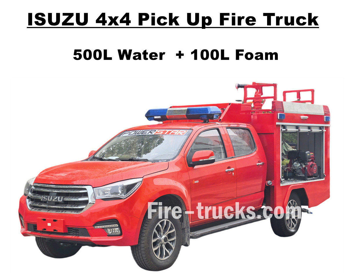
Заводская распродажа Внедорожный пикап ISUZU 4x4 пожарная машина Используемая полноприводная рама ISUZU TAGA, эта пожарная машина оснащена превосходной силовой установкой, позволяющей преодолевать любые сложные дороги. Пожарно-спасательный пикап Isuzu оборудован полностью стальной цистерной из нержавеющей стали SS304, включающей резервуар для воды на 500 литров и резервуар для пены на 100 литров, а также профессиональным независимым пожарным насосом JBQ4.5/9, установленным в задней части насосной станции, с большой дальностью распыления и опциональной панелью управления. Предлагается множество дополнительных конфигураций для удовлетворения различных потребностей, а также установлен пожарный монитор PS20 для струйной очистки водой. Этот пожарный пикап ISUZU мощностью 143 л.с. обеспечивает надежную гарантию пожарной безопасности и демонстрирует превосходные характеристики и универсальность. Оригинальная двухрядная кабина пожарного автомобиля Isuzu обеспечивает достаточно места и качества для загрузки противопожарного оборудования и поддержания хороших ходовых качеств. Кабина вмещает 5 пожарных и оборудована кондиционером, обеспечивающим комфорт водителя в любых погодных условиях. Все это гарантирует, что пожарная машина ISUZU 600L с пеной является идеальным средством пожаротушения для рынка Албании. Ниже приведено руководство пользователя, обеспечивающее безопасную эксплуатацию и работу. » I. Основные характеристики пожарного пикапа Isuzu: ★ Двигатель 4KH1 мощностью 105 кВт / 143 л.с., пробег 100 000 км без проблем. ★ ISUZU TAGA новая кабина пикапа, европейский дизайн ★ Оригинальная двухместная кабина, вмещающая 5 пожарных ★ Независимый пожарный насос JBQ4.5/9, сверхнадежный ★ Верхняя огневая пушка PS8/20, долговечная » II. Обзор комплектации пожарной машины: Внедорожный пожарный автомобиль ISUZU 4x4 AWD с системой подачи воды и пены — это вездеходный пожарно-спасательный автомобиль, предназначенный для работы в различных районах, включая населенные пункты, леса, заводы и т. д. Благодаря своим внедорожным возможностям и компактным размерам, этот пикап Isuzu способен успешно выполнять множество задач. Для повышения универсальности наших пожарных автомобилей ниже представлены варианты комплектации для различных клиентов. ----- Материал танкера : Углеродистая сталь, нержавеющая сталь, алюминиевый сплав, полипропилен ----- Пожарный насос : В зависимости от типа танкера и дальности струйной очистки, опционально американский Дарли бренд ----- Необязательный: Трубопровод, шланговая катушка, алюминиевая лестница, модель Joint (китайского, европейского, американского типа) » Ⅲ. Привлекательный внешний вид: Пожарный пикап ISUZU 4x4 AWD — мощный и маневренный автомобиль, способный быстро добраться до места пожара и легко преодолевать сложную местность. Мощная пожарная пушка имеет большую дальность стрельбы и высокую производительность, а длинный 50-метровый пожарный рукав с пушкой позволяет точно поражать очаг возгорания и эффективно покрывать и изолировать е...
Подробности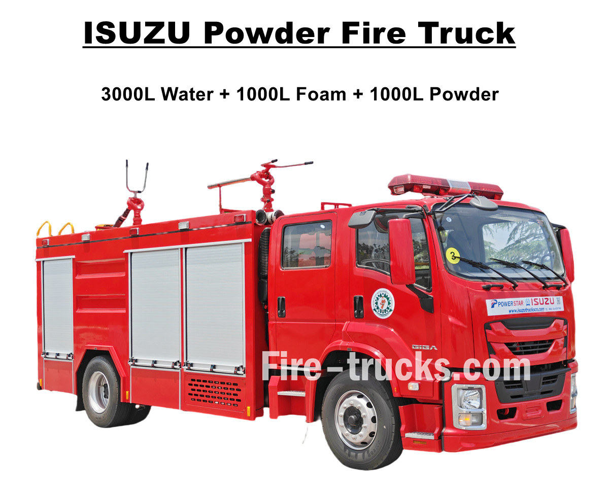
Недавно разработанный и изготовленный Пожарный автомобиль ISUZU GIGA 4X с водопенным порошковым огнетушением Высокопроизводительная пожарная машина ISUZU, экспортируемая в Нигерию (Лагос), оснащена дизельным двигателем 4HK1-TCG60 мощностью 150 кВт/205 л.с. и рабочим объемом 5193 куб. см., в сочетании с механической коробкой передач MLD с 6 скоростями, 6 передачами переднего хода и 1 передачей заднего хода, обеспечивает эффективную выходную мощность и низкий расход топлива, а также обеспечивает более быстрое реагирование и стабильное вождение. Пожарная машина Isuzu 5000L оснащена полным комплектом кузова для автоцистерны объемом 5000 л, включающим в себя цистерну для воды объемом 3000 л, цистерну для пены объемом 1000 л и цистерну для сухого порошка объемом 1000 л. Все автоцистерны изготовлены из нержавеющей стали SS304, имеют квадратную форму с внутренней перегородкой, верхнюю часть, совмещенную с крышкой люка DN500 и замком для безопасности. Пожарные автомобили Isuzu с порошковым насосом оснащены пожарным насосом CB10/40 с эффективной производительностью 40 л/с, совместимым с лафетным стволом PL8/32 с эффективной производительностью водопенной смеси 32 л/с. Кроме того, пожарный автомобиль ISUZU Giga 4X идеально подходит для тушения пожаров и спасения людей, а также для эффективной работы в Лагосе, Нигерия. Кроме того, автомобиль оснащен цистерной для сухого порошка серии R25-006, рассчитанной на давление 1,55 МПа и объем 1000 литров, а также эффективными баллонами с азотом. Для обеспечения высокой эффективности работы пожарных автомобилей ISUZU, ниже прилагается руководство по эксплуатации оборудования для клиентов из Нигерии. ♦ Пожарный автомобиль ISUZU GIGA с порошковой системой пожаротушения ♦ Руководство по эксплуатации пожарной машины с сухим порошком POWERSTAR ISUZU, экспорт в Нигерию Панель управления пожарных машин ISUZU Подробный компонент пожарной машины ISUZU » I. Основные характеристики пожарной машины Isuzu: ★ Двигатель 4HK1 мощностью 205 л.с., пробег 100 000 км без проблем. ★ ISUZU GIGA новая модель 4X кабина, европейский дизайн ★ Мост по технологии ISUZU, идеально подходящий для АФРИКИ. ★ Известный китайский насос CB10/40, супернадежный ★ Высококачественная огневая пушка PL8/32, отличающаяся прочностью. ★ Сборка сухого порошка, соответствующие баллоны с азотом » Ⅱ.Производитель пожарной машины ISUZU: Пожарный автомобиль ISUZU GIGA с системой водяного пенного и порошкового пожаротушения — это полнофункциональный пожарный автомобиль среднего размера, сочетающий в себе высокую мобильность, большой запас огнетушащего вещества и разнообразные боевые возможности. В качестве силового агрегата он оснащен двигателем Weichai в паре с трансмиссией Sinotruk, обеспечивающими высокую мощность и эффективную передачу мощности. ----- Материал танкера : Углеродистая сталь, нержавеющая сталь, алюминиевый сплав, полипропилен ----- Пожарный насос : В зависимости от типа танкера и дальности струйной очистки, опционально американский Дарли бренд ----- Н...
Подробности
Клиенты из Молдовы приобрели 6 единиц Пожарно-спасательный автомобиль для аэропорта Isuzu GIGA 4X Компания POWERSTAR TRUCKS предоставляет услуги по пожаротушению в различных районах. Полностью использует оригинальное шасси грузовика ISUZU GIGA 4X, модернизирует двухрядную кабину GIGA 4X с передними сиденьями 2+1 (обычные) и задними сиденьями 4 для дыхательных аппаратов SCBA. Кабина оборудована кондиционером с функциями обогрева и охлаждения для комфортной езды. Оснащен японским дизельным двигателем ISUZU 4HK1-TCG60 мощностью 151 кВт / 205 л.с., представляющим собой четырехцилиндровый, четырехтактный двигатель с водяным охлаждением, турбонаддувом и промежуточным охлаждением, расчетный рабочий объем стандарта 5193 куб.см., работает в паре с 6-ступенчатой механической коробкой передач ISUZU MLD, с 6 передачами вперед и 1 передачей назад, очень низкий расход топлива, всего установлено 7 единиц бескамерных шин модели 295/80R22.5, отлично подходит для различных дорожных условий. Пожарная машина Isuzu объемом 5000 л с водой и 1000 л с пеной Завод POWERSTAR является профессиональным производителем в области грузовых автомобилей, Гарантируем, что вся продукция абсолютно новая и высокого качества. » Ⅰ . Применение в пожаротушении: Новая пожарная машина ISUZU GIGA 4X мощностью 205 л.с., оснащенная полным комплектом противопожарного оборудования и средствами спасения людей, обеспечивает эффективную дальность и расход струи воды и пены, подходит для тушения различных пожаров в городах, на заводах, в жилых районах и т.д. Подробное описание передовых характеристик приведено ниже: 1. Грузовик ISUZU GIGA 4X: Японская модель ISUZU 4HK1-TCG60 с дизельным двигателем мощностью 151 кВт / 205 л.с. 2. Танкер для перевозки материалов SS304: Изготовлены на заказ водовоз объемом 5000 л и пеноцистерна объемом 1000 л из нержавеющей стали SS304. 3. Пожарный насос CB10/40: Установлен сзади, с отдельным помещением, доступна функция накачки и откачки. Пожарный насос CB10/40 Модель : КБ10/40 Давление : 1,0 МПа Макс. рабочее давление : 1,38 МПа Скорость потока : 40 л/с при 1,0 МПа, скорость 3330±50 об/мин, мощность 60 кВт, глубина всасывания 3 м. 28 л/с при 1,3 МПа, скорость вращения 3540±50 об/мин, мощность 59 кВт, глубина всасывания 3 м. 20 л/с при 1,0 МПа, скорость вращения 3335±50 об/мин, мощность 42 кВт, глубина всасывания 7 м. Коэффициент скорости : 1:1.542 4. Пожарный монитор PL8/36: Модель с верхним расположением, ручным управлением и дальностью распыления более 55 м, эффективная и долговечная. Пожарный монитор PL8/36 Модель : ПЛ8/36 Давление : 0,8 МПа Рабочий диапазон : Пена ≥ 60 м и вода ≥ 48м Вертикальное вращение : -45° ~ +70° Горизонтальное вращение : 0° ~ 360° Скорость потока : 36 л/с 5. Интегрированный Устройство управления Пожарные машины ISUZU, оснащенные встроенным устройством управления в заднем насосном отделении, удобны и интеллектуальны. » Ⅱ Расширенные возможности пожарной машины: Пожарная машина ISUZU GIGA 4X повышенной грузоподъемности идеально подходит дл...
Подробности
Пожалуйста, читайте дальше, оставайтесь на связи, подписывайтесь, и мы будем рады узнать ваше мнение.

 Specated Ipv6 Network

 русский
 English
 français
 Deutsch
 italiano
 español
 português
 Nederlands
 العربية
 日本語
日本語 한국의
한국의 Türkçe
 Melayu
 ไทย
ไทย Tiếng Việt
 Indonesia
  中文
中文 қазақ
қазақ Filipino
 မြန်မာ
 српски